Free/Libre and Open Source Software Stack for the NAND LAND Go Board
Field programmable gate arrays (FPGAs) are cool. You can write software for processors, but you can write hardware for FPGAs. A hardware description language (HDL) can describe the layout of arbitrary digital chips, like a floating point unit or a central processor, and then the description can be compiled and uploaded into a FPGA.
Unfortunately, the barrier to entry is higher than for software. With software, you can always install Python and get going in a few seconds. Testing is as easy as print statements. With FPGAs, it's hard to do anything worthwhile without hardware. There are blog posts and textbooks, but I didn't know of any all-in-one guide that focused on making things.
In September 2023, No Starch Press published Russel Merrick's Getting Started with FPGAs. I was excited to hear this. I studied computer engineering—not science—in school, so I had hands on experience with digital design, but hadn't gotten a chance to do any for work. Besides playing with Icarus Verilog, I hadn't done any digital design at all. In addition, I had just finished some digital design training at work and I was itching to do a project that would help me retain and expand on that training: reimplementing my custom virtual machine in hardware.
Sadly, Merrick's book uses Windows tooling. To quote ESR, "Trying to learn to hack on a Microsoft Windows machine or under any other closed-source system is like trying to learn to dance while wearing a body cast." FPGAs on Windows stings less than software on Windows, since you don't need to rely much on your host operating system—you're basically cross compiling—but learning Windows makes it more likely Windows will be a larger part of my career, and I want to avoid that.
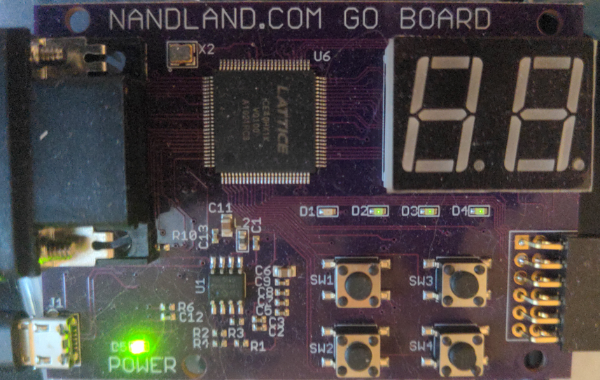
The Go Board, a $70 board designed by Merrick and compatible with the book, uses a Lattice ICE40 FPGA: a FPGA that a libre toolchain already exists for. There's no reason why the instructions couldn't use free tooling and, looking at the book, a reader could follow most of the instructions while using free software. The only catch is that the free tooling only supports Verilog, one of the two major hardware description languages. The other, VHDL, isn't supported. Merrick gives examples in both Verilog and VHDL, but to follow along with a libre toolchain, the user will need to stick to the Verilog snippets.
Below is a simple snippet for a Makefile:
test.bin: test.txt
	icepack test.txt test.bin

test.txt: test.blif test.pcf
	arachne-pnr -p test.pcf -P vq100 test.blif -o test.txt

test.blif: test.v
	yosys -blif test.blif test.v

install: test.bin
	iceprog test.bin
All these programs are availiable for Debian through aptitude; they're an apt-get away.
The build process is broken into three steps. First, yosys will synthesize your Verilog source, test.v, into a Berkeley Logic Interchange Format (BLIF) file, test.blif: a netlist of the design. Second, we use arachne-pnr to covert the netlist, test.blif, into a bitstream, an intermediate format, that can later be packed and transmitted to the machine. The arachne-pnr command needs to know which physical device pins are tied to the input and output wires of your design. The pin constraints file (PCF), test.pcf, contains this mapping. The pin constraints are not enough by themselves. The same FPGA can be packaged in multiple ways. The Go Board uses a vq100 layout. I didn't see this written down anywhere, but vq100 is written on center of the Go Board's FPGA chip: the large chip with "LATTICE" written on it. Finally, with the bitstream written to an output file, test.txt, it can be packed with the icepack command. There are no tricks here, it's very straightforward. At this point, you design is stored in test.bin and ready to upload.
Besides finding the layout, the only other part I was confused with was format for the PCF file. It's needed for I/O. Merrick's book has some definitions, but I never found where he got them. A copy of the test.pcf from my test program.
# LED pins:
set_io o_LED_1 56
set_io o_LED_2 57
set_io o_LED_3 59
set_io o_LED_4 60
# Push-button switches:
set_io i_Switch_1 53
set_io i_Switch_2 51
set_io i_Switch_3 54
set_io i_Switch_4 52
Now if the top level module has an output o_LED_1, it will be tied pin 56: an LED pin.
To load the device to your board, it's enough to just type iceprog test.bin. Happy hacking!